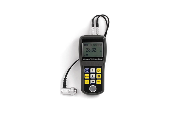
Features of UT500A Ultrasonic Thickness Gauge
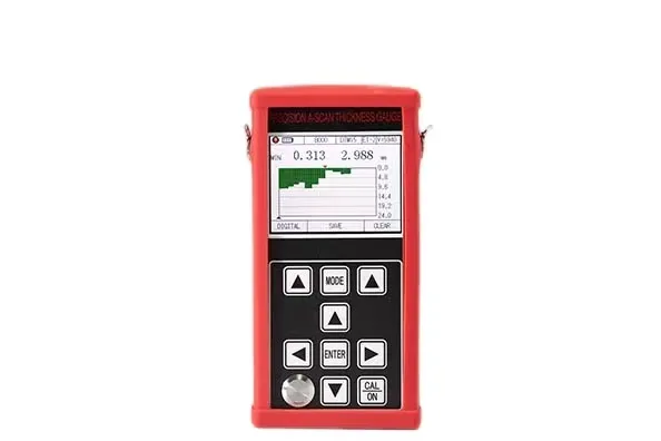
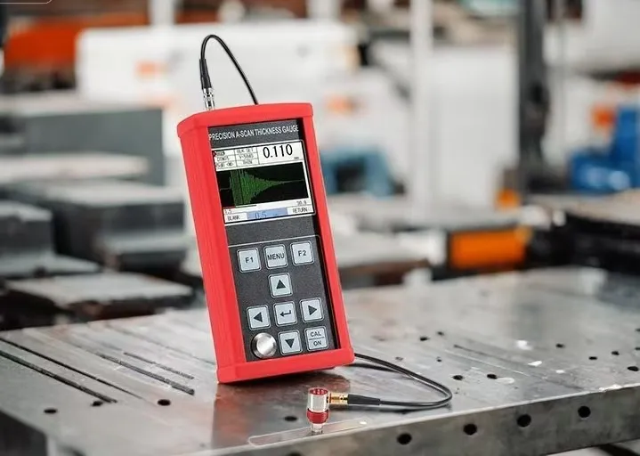
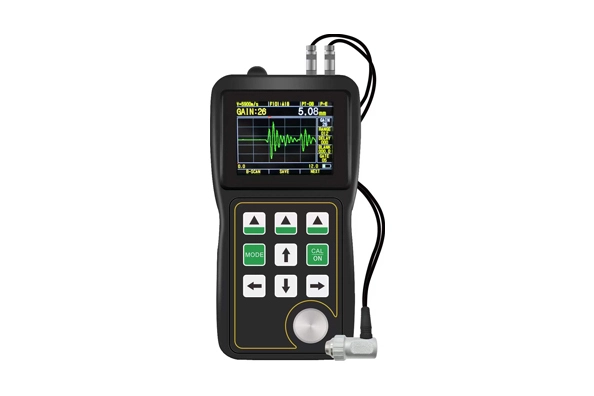
UT500A has A-scan mode, B-scan mode and numerical display mode;
The measurement range is wide, and the unique "multiple echo" technology is adopted to realize the measurement of ultra-thin parts, with a minimum measurement thickness of 0.12mm (steel);
This product can measure the thickness with high precision, and the maximum measurement resolution can reach 0.001mm; The repetition resolution can reach ± 0.002mm;
UT500A has the functions of penetrating coating and echo to echo measurement, which is used to measure materials with paint layer and coating on the surface;
Multiple measurement modes: mb-e, E-E and auto modes meet the measurement of conventional thick workpieces; Thin mode realizes the measurement of thin parts;
Numerical modes include: conventional thickness value mode, difference / reduction rate mode and maximum value mode;
Two gain modes: automatic gain / manual gain;
Manual shutdown and automatic shutdown can be set, with energy-saving function;
UT500A supports a variety of probes, including double crystal probe and single crystal probe, and supports up to 20MHz high-frequency probe;
It supports mass storage and can store 100000 thickness values, 500 groups of A-scan waveforms and 500 groups of B-scan waveforms at the same time;
Large 3.5-inch color TFT-LCD display;
UT500A has a variety of calibration methods, supports one-point calibration, multi-point calibration and manual calibration modes, and can calibrate sound velocity and probe zero position at the same time; It supports v-path correction of double crystal probe.
It supports the conversion of metric and British system; It can switch between millimeter and inch units;
UT500A supports Chinese and English display;
Applicable Materials
It is suitable for measuring the thickness of metals (such as steel, cast iron, aluminum, copper, etc.), plastics, ceramics, glass, resin, glass fiber and other good ultrasonic conductors.
Basic Principle
The principle of ultrasonic thickness measurement is similar to that of light wave measurement. The ultrasonic pulse emitted by the probe reaches the measured object and propagates in the object. When it reaches the material interface, it is reflected back to the probe. The thickness of the measured material is determined by accurately measuring the time of ultrasonic propagation in the material.
Parameters of UT500A Ultrasonic Thickness Gauge
Item | UT500A |
Probe type | Single crystal probe / double crystal probe |
Measuring range (45# steel) | 0.11mm – 1800mm |
Indication stability | Zero crossing and multiple echo technology are adopted to ensure that the thickness measurement value is not affected by echo strength, material attenuation coefficient, gain and gate height, and has high measurement stability and reliability. |
Measurement frequency | 4Hz、8Hz、16Hz |
Resolution | 0.1mm、0.01mm、0.001mm(0.01inch、0.001inch、0.0001inch) |
Pulse generator | Negative square wave emission is adopted, and the pulse width and voltage are automatically matched with the probe. |
Sound velocity range | 400-19999m/s |
Calibration block | 4mm(steel) |
Automatic shutdown | One can choose 5 minutes, 10 minutes, 20 minutes and manual shutdown. |
Probe calibration | One point calibration, multi-point calibration |
gain | Automatic gain control, Manual gain control |
Gain range | 0~80dB |
Detection mode | Radio frequency (RF), positive half wave (POS), negative half wave (NEG), full wave (FULL) |
Measurement mode | (1) MB-E: the measurement mode based on the transit time from the initial echo to the first bottom echo; (2) E-E: penetration coating measurement mode, the arbitrary Em–En echo is optional; (3) ME-E: multiple echo measurement mode; (4) THIN: thin wall measurement mode; |
Numerical mode | Thickness value mode, difference / reduction rate mode, maximum / minimum value mode |
A-scan mode | Available |
B-scan mode | Available |
Coupling indication | Available |
Battery Indication | Available |
Language | English |
Unit | mm/inch |
Menu operation | Available |
Software function | Dynamic gate setting, blanking setting (Blank), echo blanking setting (E-blank), echo freezing, echo translation and scaling |
Storage function | It can store 100,000 thicknesses (100 groups, 1000 in each group), 500 groups of A-scan waveforms and 500 groups of B-scan waveforms at the same time. |
Host program upgrade | Available |
Display | 3.5 " color TFT-LCD screen |
Data transmission | It supports RS-232 serial communication and transmits data to the computer. |
Working temperature | -10℃~+50℃; With special requirements, it can reach - 20 ℃; |
Working voltage | 3 No. 5 AA batteries are required. When the power is insufficient, there is a low voltage prompt. |
Overall dimension | 164 x 85 x 32 (mm) |
Total Weight | 260 g(With battery) |
Probe Technical Parameters of UT400 Ultrasonic Thickness Gauge
Ultrasonic thickness
Probe | Characteristic | Measurement Range(steel) | Diameter | Frequency | Contact temperature (℃) |
5PΦ10 | Universal probe | 1.2~225mm | 10mm | 5MHz | -10~+50 |
7PΦ6 | Small diameter tube | 0.75~60mm 15×2.0mm(steel) | 6mm | 7MHz | -10~+50 |
TSTU32 | High penetration | 5.0~40mm(cast iron) | 22mm | 2MHz | -10~+50 |
SZ2.5P | High penetration | 3.0~300mm(steel) | 14mm | 2.5MHz | -10~+50 |
ZW5P | High temperature resistance | 4.0~80mm(steel) | 12mm | 5MHz | -10~+300 |
2PΦ20 | High penetration | 4~500mm | 12mm | 2.5MHz | -10~+50 |
UT400 Function Detailed Explanation
If you encounter problems that cannot be solved by ordinary thickness gauge, please choose our UT400 ultrasonic thickness gauge, which can solve various thickness measurement problems to the greatest extent and provide you with cost effective solutions.
Ordinary ultrasonic thickness gauges using the [pulse-echo method] principle need to meet the following two conditions to successfully measure:
1. The first bottom echo is higher than the gate (the gate level is fixed and cannot be adjusted).
2. No other clutter is higher than the gate before the first bottom echo.(Otherwise, the measured thickness will be the thickness where the cluster is generated) Sometimes, the above requirements cannot be met in many cases:
Such as high corrosion near the surface, coarse-grained materials (such as cast iron), aluminum materials, small-diameter tubes, ultra-thin plates, ultra-thick plates, rough surface, uneven internal materials, internal defects, laminated structure, etc. Ordinary ultrasonic thickness gauges will be powerless.
UT400 Can Easily Solve the Following Problems
1. The first bottom echo can be higher than the gate by adjusting the gain and gate height.
2. Other clutter before the first bottom echo can be invalidated through the blanking function.
Live Color A-Scan:
The user can directly see the wave pattern of color ultrasonic signal (or A-scan) on the screen, which is very important for the occasion where it is necessary to verify whether the thickness reading is correct. Many cases may lead to wrong thickness readings or even no readings. The problem can be easily found according to the waveform, and then the correct thickness readings can be obtained by properly adjusting the gain, blanking and gate parameters according to the waveform. Use of waveform: verify the thickness reading according to the waveform, find the problem according to the waveform, seek a solution according to the waveform, and adjust the parameters according to the waveform to solve the problem.


 français
 Español
 русский
 العربية
 português